


Port Identification Guide
Abbreviations
| NPTF | National Pipe Tapered Fuel |
| NPSM | National Pipe Straight Mechanical |
| ISO | International Standards Organization |
| SAE | Society of Automotive Engineers |
| JIC | Joint Industrial Council |
| NFPA | National Fluid Power Association |
| BSP | British Standard Pipe |
| DIN | Deutsche Industrial Norme |
| JIS | Japanese Industrial Standard |
| BSPT | British Standard Pipe Tapered |
| BSPP | British Standard Pipe Parallel |
Introduction
Because connectors and ports have many applications in fluid piping systems, you need to correctly identify them before adding or replacing them on a tube or hose, in your specific application.
Manufacturers use identifiers such as ASME B1 .1 and ISO 261, to classify the main thread characteristics: pitch, angle, diameter, and form. Some organizations that are developing these, are the International Organization for Standardization, SAE International, British Association, and Deutsches Institut für Normung, and the American Society of Manufacturing Engineers, American National Standards Institute.
Port and Connector Identification Tools
CalipersUsed for measuring inner and outer diameters of threads
Thread Pitch Gauge
Used to measure the amount of threads per inch, as well as the thread to thread spacing in metric applications.
Accurate measurement of threads
Before you start measuring the threads of your fluid pipe or tube, ensure that they are in good conditions. Distorted or worn out threads can give you inaccurate measurements. After confirming that your threads are in good conditions, measure their diameter and record. An I.D./O.D. caliper is a suitable tool for this. Match the dimensions provided in this guide with your recorded measurements.
It is important to note that your measurements may not accurately match with the values provided in this guide. The slight differences are mainly caused by manufacturing tolerances.
After measuring the diameter of your threads, determine their spacing in threads per inch. In the case of metric connections, measure the thread-to-thread distances. To get an accurate value, ensure that the thread pitch gauge is fitting well on the threads. Record the values and compare your measurements with the figures provided in this guide.
Accurate measurement of four-bolt flanges
Begin by using a caliper to measure the port hole diameter the bolt. Once you make a note of that, measure the distance from center to center of the bolt holes, noting the longest spacing.
Dash numbers
The sizes of tubes and fluid pipes are generally identified by abbreviations known as dash numbers, and are commonly used when ordering parts. When using a dash number to identify a fluid pipe or a tube, the numerator part of the fraction is just used. The denominator (which is always 16) is generally ignored. For example, 8/16" or 1/2" equates to size -8 . Note: dash numbers are nominal.
Since metric measurements give the true sizes of a tube or a fluid pipe, dash numbers do not apply for them. For example, for M12x1.0, the outer diameter of the threads is 12 mm with a 1.0 mm spacing between threads.
American Connections
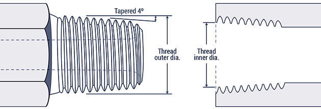
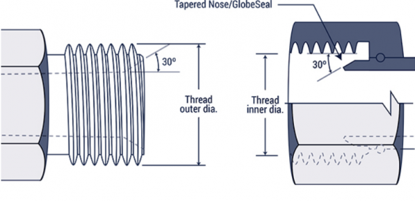
National Pipe Tapered Fuel (NPTF)
The male and female threads connect and a seal is formed when the two are mated together (i.e. threads deformation). This is known as a dry seal thread. If additional sealing is required, teflon and pipe dope can be applied. The National Fluid Power Association (NFPA) does not recommend the connection for hydraulic applications, however it is commonly found in fluid piping systems
Note: Both the NPTF and BSPT connectors appear similar, however the two are not interchangeable.
| Inch size | Dash size | Threads per Inch | Male Thread O.D. (in) | Female thread O.D (in) | ||
| 1⁄8 | -2 | 27 | 13⁄32 | 0.41 | 3⁄8 | 0.38 |
| 1⁄4 | -4 | 18 | 17⁄32 | 0.54 | 1⁄2 | 0.49 |
| 3⁄8 | -6 | 18 | 11⁄16 | 0.68 | 5⁄8 | 0.63 |
| 1⁄2 | -8 | 14 | 27⁄32 | 0.84 | 25⁄32 | 0.77 |
| 3⁄4 | -12 | 14 | 1 1⁄16 | 1.05 | 1 | 0.98 |
| 1 | -16 | 11 1⁄2 | 1 5⁄16 | 1.32 | 1 1⁄4 | 1.24 |
| 1 1⁄4 | -20 | 11 1⁄2 | 1 21⁄32 | 1.66 | 1 19⁄32 | 1.58 |
| 1 1⁄2 | -24 | 11 1⁄2 | 1 29⁄32 | 1.90 | 1 13⁄16 | 1.82 |
| 2 | -32 | 11 1⁄2 | 2 3⁄8 | 2.38 | 2 5⁄16 | 2.30 |
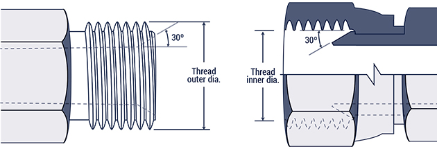
National Pipe straight mechanical (NPSM)
Both male and female NSPM connectors' threads are straight, while the male has a 300 internal chamfer, the female has an inverted 300 seat. A mechanical connection is made when the both male and female are mated together. The tapered seat creates a leak-resistant connection, and are commonly found in fluid power systems.
Note: A NPSM female can seal together with a chamfered NPTF male.
| Inch size | Dash size | Threads per Inch | Male Thread O.D. (in) | Female thread O.D (in) | ||
| 1⁄8 | -2 | 27 | 13⁄32 | 0.41 | 3⁄8 | 0.38 |
| 1⁄4 | -4 | 18 | 17⁄32 | 0.54 | 1⁄2 | 0.49 |
| 3⁄8 | -6 | 14 | 11⁄16 | 0.68 | 5⁄8 | 0.63 |
| 1⁄2 | -8 | 14 | 27⁄32 | 0.84 | 25⁄32 | 0.77 |
| 3⁄4 | -12 | 14 | 1 1⁄16 | 1.05 | 1 | 0.98 |
| 1 | -16 | 11 1⁄2 | 1 5⁄16 | 1.32 | 1 1⁄4 | 1.24 |
| 1 1⁄4 | -20 | 11 1⁄2 | 1 21⁄32 | 1.66 | 1 19⁄32 | 1.58 |
| 1 1⁄2 | -24 | 11 1⁄2 | 1 29⁄32 | 1.90 | 1 13⁄16 | 1.82 |
| 2 | -32 | 11 1⁄2 | 2 3⁄8 | 2.38 | 2 5⁄16 | 2.30 |
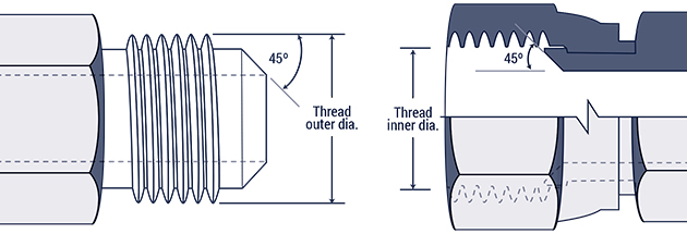
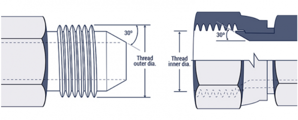
JIC 37° Flare (SAE J514)
Widely found in hydraulic systems, both the JIC male and JIC female of this connection have a 37º flare seat as well as straight threads. The flare seats of the male and female seal together when the straight threads are joined. The straight threads of the each half hold the connection together mechanically.
Note: While most SAE J514 threads look identical to SAE 45º flare threads, their seating angles do not match.

| Inch size | Dash size | Thread Size | Male Thread O.D. (in) | Female thread O.D (in) | ||
| 1⁄8 | -2 | 5⁄16 - 24 | 5⁄16 | 0.31 | 9⁄32 | 0.27 |
| 3⁄16 | -3 | 3⁄8 - 24 | 3⁄8 | 0.38 | 11⁄32 | 0.34 |
| 1⁄4 | -4 | 7⁄16 - 20 | 7⁄16 | 0.44 | 13⁄32 | 0.39 |
| 5⁄16 | -5 | 1⁄2 - 20 | 1⁄2 | 0.50 | 15⁄32 | 0.45 |
| 3⁄8 | -6 | 9⁄16 - 18 | 9⁄16 | 0.56 | 17⁄32 | 0.51 |
| 1⁄2 | -8 | 3⁄4 - 16 | 3⁄4 | 0.75 | 11⁄16 | 0.69 |
| 5⁄8 | -10 | 7⁄8 - 14 | 7⁄8 | 0.88 | 13⁄16 | 0.81 |
| 3⁄4 | -12 | 1 1⁄16 - 12 | 11⁄16 | 1.06 | 1 | 0.98 |
| 7⁄8 | -14 | 1 3⁄16 - 12 | 1 3⁄16 | 1.19 | 1 1⁄8 | 1.10 |
| 1 | -16 | 1 5⁄16-12 | 1 5⁄16 | 1.31 | 1 1⁄4 | 1.23 |
| 1 1⁄4 | -20 | 1 5⁄8 - 12 | 1 5⁄8 | 1.63 | 1 9⁄16 | 1.54 |
| 1 1⁄2 | -24 | 1 7⁄8 - 12 | 1 7⁄8 | 1.88 | 1 13⁄16 | 1.79 |
| 2 | -32 | 2 1⁄2 - 12 | 2 1⁄2 | 2.50 | 2 7⁄16 | 2.42 |
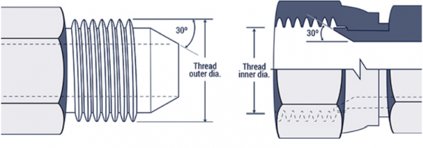
SAE 45° Flare (SAE J512)
These connectors are widely found in low pressure applications like refrigerant and fuel lines, as well as automotive piping applications. Both halves have a 45° flare seat, and the threads of the each connector engage together to form a tight mechanical connection, with the seal forming on the 45° flare seat.
Note: SAE 45° Flare connectors are identical to JIC 37° Flare connectors, except for the angles of the seats.
| Inch size | Dash size | Thread Size | Male Thread O.D. (in) | Female thread O.D (in) | ||
| 1⁄8 | -2 | 5⁄16 - 24 | 5⁄16 | 0.31 | 9⁄32 | 0.27 |
| 3⁄16 | -3 | 3⁄8 - 24 | 3⁄8 | 0.38 | 11⁄32 | 0.34 |
| 1⁄4 | -4 | 7⁄16 - 20 | 7⁄16 | 0.44 | 13⁄32 | 0.39 |
| 5⁄16 | -5 | 1⁄2 - 20 | 1⁄2 | 0.50 | 15⁄32 | 0.45 |
| 3⁄8 | -6 | 5⁄8 - 18 | 5⁄8 | 0.63 | 9⁄16 | 0.57 |
| 1⁄2 | -8 | 3⁄4 - 16 | 3⁄4 | 0.75 | 11⁄16 | 0.69 |
| 5⁄8 | -10 | 7⁄8 - 14 | 7⁄8 | 0.88 | 13⁄16 | 0.81 |
| 3⁄4 | -12 | 1 1⁄16 - 14 | 11⁄16 | 1.06 | 1 | 0.99 |
| 7⁄8 | -14 | 1 1⁄4 - 12 | 1 1⁄4 | 1.25 | 1 5⁄32 | 1.16 |
| 1 | -16 | 1 3⁄8 - 12 | 1 3⁄8 | 1.38 | 1 9⁄32 | 1.29 |
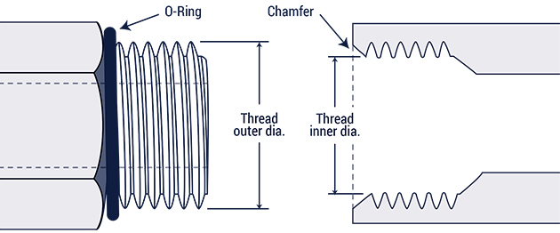
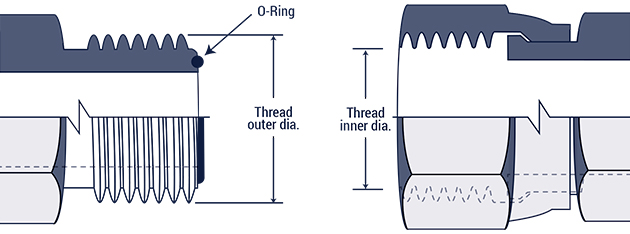
SAE Straight Thread O-ring (O-Ring Boss)
SAE J1926-1 and ISO 11296-1
The female port of the O-Ring Boss has a sealing face, chamfer, and a straight thread. The male connector has an O-ring and a straight thread. The seal is made when the O-ring is squeezed into the chamfer. The male and female threads bind together to make a mechanically strong connection. This connection is common in high pressure hydraulic systems.
| Inch size | Dash size | Thread Size | Male Thread O.D. (in) | Female thread O.D (in) | ||
| 1⁄8 | -2 | 5⁄16 - 24 | 5⁄16 | 0.31 | 9⁄32 | 0.27 |
| 3⁄16 | -3 | 3⁄8 - 24 | 3⁄8 | 0.38 | 11⁄32 | 0.34 |
| 1⁄4 | -4 | 7⁄16 - 20 | 7⁄16 | 0.44 | 13⁄32 | 0.39 |
| 5⁄16 | -5 | 1⁄2 - 20 | 1⁄2 | 0.50 | 15⁄32 | 0.45 |
| 3⁄8 | -6 | 9⁄16 - 18 | 9⁄16 | 0.56 | 17⁄32 | 0.51 |
| 1⁄2 | -8 | 3⁄4 - 16 | 3⁄4 | 0.75 | 11⁄16 | 0.69 |
| 5⁄8 | -10 | 7⁄8 - 14 | 7⁄8 | 0.88 | 13⁄16 | 0.81 |
| 3⁄4 | -12 | 1 1⁄16 - 12 | 11⁄16 | 1.06 | 1 | 0.98 |
| 7⁄8 | -14 | 1 3⁄16 - 12 | 1 3⁄16 | 1.19 | 1 1⁄8 | 1.10 |
| 1 | -16 | 1 5⁄16 - 12 | 1 5⁄16 | 1.31 | 1 1⁄4 | 1.23 |
| 1 1⁄4 | -20 | 1 5⁄8 - 12 | 1 5⁄8 | 1.63 | 1 9⁄16 | 1.54 |
| 1 1⁄2 | -24 | 1 7⁄8 - 12 | 1 7⁄8 | 1.88 | 1 13⁄16 | 1.79 |
| 2 | -32 | 2 1⁄2 - 12 | 2 1⁄2 | 2.50 | 2 7⁄16 | 2.42 |
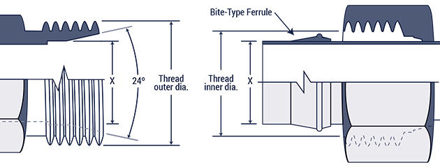
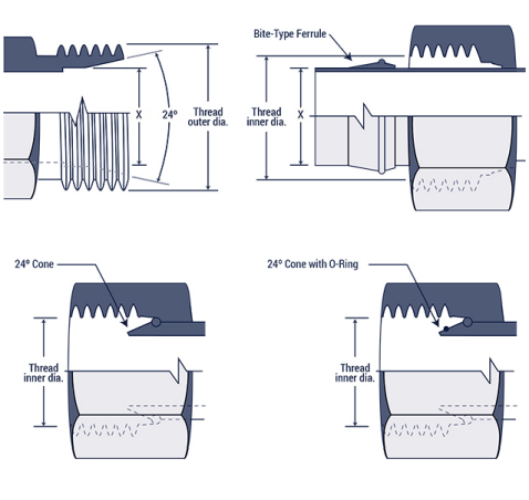
Flareless Compression (SAE J514)
The male half of this connection has a 240 seat with a straight thread. The female has a compression sleeve with a straight thread. Along with the sleeve, a female nut and tube partly form the female connection. With the male half, the seal forms between the 24O seat and the compression sleeve. With the female half, the seal forms between the tubing and compression sleeve. The threads mesh together to form a mechanically strong bond.
| Inch size | Dash size | Thread Size | Male Thread O.D. (in) | Female thread O.D (in) | ||
| 1⁄8 | -2 | 5⁄16 - 24 | 5⁄16 | 0.31 | 9⁄32 | 0.27 |
| 3⁄16 | -3 | 3⁄8 - 24 | 3⁄8 | 0.38 | 11⁄32 | 0.34 |
| 1⁄4 | -4 | 7⁄16 - 20 | 7⁄16 | 0.44 | 13⁄32 | 0.39 |
| 5⁄16 | -5 | 1⁄2 - 20 | 1⁄2 | 0.50 | 15⁄32 | 0.45 |
| 3⁄8 | -6 | 9⁄16 - 18 | 9⁄16 | 0.56 | 17⁄32 | 0.51 |
| 1⁄2 | -8 | 3⁄4 - 16 | 3⁄4 | 0.75 | 11⁄16 | 0.69 |
| 5⁄8 | -10 | 7⁄8 - 14 | 7⁄8 | 0.88 | 13⁄16 | 0.81 |
| 3⁄4 | -12 | 1 1⁄16 - 12 | 11⁄16 | 1.06 | 1 | 0.98 |
| 7⁄8 | -14 | 1 3⁄16 - 12 | 1 3⁄16 | 1.19 | 1 1⁄8 | 1.10 |
| 1 | -16 | 1 5⁄16 - 12 | 1 5⁄16 | 1.31 | 1 1⁄4 | 1.23 |
| 1 1⁄4 | -20 | 1 5⁄8 - 12 | 1 5⁄8 | 1.63 | 1 9⁄16 | 1.54 |
| 1 1⁄2 | -24 | 1 7⁄8 - 12 | 1 7⁄8 | 1.88 | 1 13⁄16 | 1.79 |
| 2 | -32 | 2 1⁄2 - 12 | 2 1⁄2 | 2.50 | 2 7⁄16 | 2.42 |
O-Ring Face Seal (SAE J1453)
This connection forms an impressive leak resistance and can be used in applications up to 6000 psi. The male half of the connection has an O-ring with a straight thread. The female half has a machined flat surface with a straight thread. A seal takes place when the O-ring on the male end is squeezed onto the female flat surface seat. The swivel nut on the female half holds the connection together.
| Inch size | Dash size | Thread Size | Male Thread O.D. (in) | Female thread O.D (in) | ||
| 1⁄4 | -4 | 9⁄16 - 18 | 9⁄16 | 0.56 | 17⁄32 | 0.51 |
| 3⁄8 | -6 | 11⁄16 - 16 | 11⁄16 | 0.69 | 5⁄8 | 0.63 |
| 1⁄2 | -8 | 13⁄16 - 16 | 13⁄16 | 0.82 | 3⁄4 | 0.75 |
| 5⁄8 | -10 | 1 - 14 | 1 | 1.00 | 15⁄16 | 0.93 |
| 3⁄4 | -12 | 1 3⁄16 - 12 | 13⁄16 | 1.19 | 1 1⁄8 | 1.11 |
| 1 | -16 | 1 7⁄16 - 12 | 1 7⁄16 | 1.44 | 1 3⁄4 | 1.36 |
| 1 1⁄4 | -20 | 1 11⁄16 - 12 | 1 11⁄16 | 1.69 | 1 5⁄8 | 1.61 |
| 1 1⁄2 | -24 | 2-12 | 2 | 2.00 | 1 15⁄16 | 1.92 |
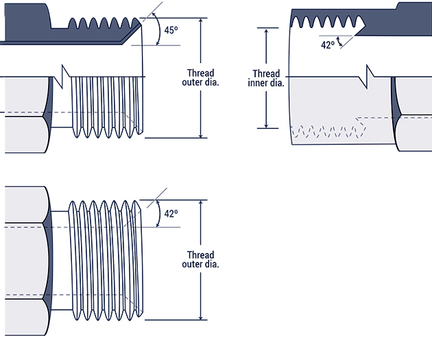
SAE Inverted Flare (SAE J512)
Widely used in automotive systems, the inverted flare connection features a machined male connector with a 420 seat, and a flared male tubing with a 450 seat. The female side has a 420 seat that provides a sealing surface. The threads connect together to make a mechanically strong bond.
| Inch size | Dash size | Thread Size | Male Thread O.D. (in) | Female thread O.D (in) | ||
| 1⁄8 | -2 | 5⁄16 - 28 | 5⁄16 | 0.31 | 9⁄32 | 0.27 |
| 3⁄16 | -3 | 3⁄8 - 24 | 3⁄8 | 0.38 | 11⁄32 | 0.34 |
| 1⁄4 | -4 | 7⁄16 - 24 | 7⁄16 | 0.44 | 13⁄32 | 0.39 |
| 5⁄16 | -5 | 1⁄2 - 20 | 1⁄2 | 0.50 | 15⁄32 | 0.45 |
| 3⁄8 | -6 | 5⁄8 - 18 | 5⁄8 | 0.63 | 9⁄16 | 0.57 |
| 7⁄16 | -7 | 11⁄16 - 18 | 11⁄16 | 0.69 | 5⁄8 | 0.63 |
| 1⁄2 | -8 | 3⁄4 - 18 | 3⁄4 | 0.75 | 23⁄32 | 0.70 |
| 5⁄8 | -10 | 7⁄8 - 18 | 7⁄8 | 0.88 | 13⁄16 | 0.81 |
| 3⁄4 | -12 | 1 1⁄16 - 16 | 1 1⁄16 | 1.06 | 1 | 1.00 |
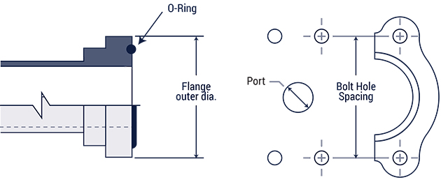
Four-Bolt Flange (SAE J518 and ISO 6162)
Commonly found in fluid power systems, the Four-Bolt Flange works well connecting 1/2" to 3" hose and tube. The seal forms between the O-ring on the male half and the smooth face of the female port (with the O-ring seating on the ring groove of the male). Two clamp halves, held by four bolts, hold the connection together.
These are available in two pressure groups: standard (code 61) and high pressure (code 62).
| Inch size | Dash size | Code 61 Bolt Spacing | Code 61 Flange O.D. | Code 62 Bolt Spacing | Code 62 Flange O.D. |
| 1⁄2 | -8 | 1 1⁄2 | 1 3⁄16 | 1 19⁄32 | 1 1⁄4 |
| 3⁄4 | -12 | 1 7⁄8 | 1 1⁄2 | 2 | 1 5⁄8 |
| 1 | -16 | 2 1⁄16 | 1 3⁄4 | 2 1⁄4 | 1 7⁄8 |
| 1 1⁄4 | -20 | 2 5⁄16 | 2 | 2 5⁄8 | 2 1⁄8 |
| 1 1⁄2 | -24 | 2 3⁄4 | 2 3⁄8 | 3 1⁄8 | 2 1⁄2 |
| 2 | -32 | 3 1⁄16 | 2 13⁄32 | 3 13⁄16 | 3 1⁄8 |
| 2 1⁄2 | -40 | 3 1⁄2 | 3 5⁄16 | n/a | n/a |
| 3 | -48 | 4 3⁄16 | 4 |
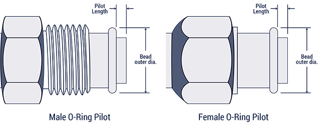
O-Ring Pilot Threads
| Inch size | Dash size | Male Thread Thread size |
Thread O.D. | Female thread Thread Size |
Thread I.D. |
| 3⁄8 | -6 | 5⁄8 - 18 | 5⁄8 | 5⁄8 - 18 | 9⁄16 |
| 1⁄2 | -8 | 3⁄4 - 18 | 3⁄4 | 3⁄4 - 18 | 1 5⁄8 |
| 5⁄8 | -10 | 7⁄8 - 18 | 7⁄8 | 7⁄8 - 18 | 13⁄16 |
| 3⁄4 | -12 | 1 1⁄16 - 16 | 1 1⁄16 | 1 1⁄16 - 14 | 1 |
| Inch size | Dash size | Long pilot Bead O.D. (in) |
Pilot Length (in) | Short pilot Bead O.D. (in) |
Pilot Length (in) |
| 3⁄8 | -6 | 0.52 | 0.28 | 0.52 | 0.19 |
| 1⁄2 | -8 | 0.64 | 0.39 | 0.64 | 0.19 |
| 5⁄8 | -10 | 0.77 | 0.39 | 0.77 | 0.19 |
| 3⁄4 | -12 | 0.91 | 0.39 | 0.91 | 0.19 |
International Connections
British Standard Pipe
British connections are available in two categories: British Standard Pipe Parallel (BSPP), and British Standard Pipe Tapered (BSPT).
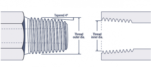
British Standard Pipe Tapered (BSPT)
| Inch size | Dash size | Thread Size | Male Thread |
|
Female thread | O.D. (in) | |
| 1⁄8 | -2 | 1⁄8 - 28 | 3⁄8 | 0.38 | 11⁄32 | 0.35 | |
| 1⁄4 | -4 | 1⁄4 - 19 | 33⁄64 | 0.52 | 15⁄32 | 0.47 | |
| 3⁄8 | -6 | 3⁄8 - 19 | 21⁄32 | 0.65 | 19⁄32 | 0.60 | |
| 1⁄2 | -8 | 1⁄2 - 14 | 13⁄16 | 0.82 | 3⁄4 | 0.75 | |
| 5⁄8 | -10 | 5⁄8 - 14 | 7⁄8 | 0.88 | 13⁄16 | 0.80 | |
| 3⁄4 | -12 | 3⁄4 - 14 | 1 1⁄32 | 1.04 | 31⁄32 | 0.97 | |
| 1 | -16 | 1 - 11 | 1 5⁄16 | 1.30 | 1 7⁄32 | 1.22 | |
| 1 1⁄4 | -20 | 1 1⁄4 - 11 | 1 21⁄32 | 1.65 | 1 9⁄16 | 1.56 | |
| 1 1⁄2 | -24 | 1 1⁄2 - 11 | 1 7⁄8 | 1.88 | 1 25⁄32 | 1.79 | |
| 2 | -32 | 2-11 | 2 11⁄32 | 2.35 | 2 1⁄4 | 2.26 |
British Standard Pipe Parallel (BSPP)
| Inch size | Dash size | Thread Size | Male Thread |
|
Female thread | O.D. (in) | |
| 1⁄8 | -2 | 1⁄8 - 28 | 3⁄8 | 0.38 | 11⁄32 | 0.35 | |
| 1⁄4 | -4 | 1⁄4 - 19 | 33⁄64 | 0.52 | 15⁄32 | 0.47 | |
| 3⁄8 | -6 | 3⁄8 - 19 | 21⁄32 | 0.65 | 19⁄32 | 0.60 | |
| 1⁄2 | -8 | 1⁄2 - 14 | 13⁄16 | 0.82 | 3⁄4 | 0.75 | |
| 5⁄8 | -10 | 5⁄8 - 14 | 7⁄8 | 0.88 | 13⁄16 | 0.80 | |
| 3⁄4 | -12 | 3⁄4 - 14 | 1 1⁄32 | 1.04 | 31⁄32 | 0.97 | |
| 1 | -16 | 1 - 11 | 1 5⁄16 | 1.30 | 1 7⁄32 | 1.22 | |
| 1 1⁄4 | -20 | 1 1⁄4 - 11 | 1 21⁄32 | 1.65 | 1 9⁄16 | 1.56 | |
| 1 1⁄2 | -24 | 1 1⁄2 - 11 | 1 7⁄8 | 1.88 | 1 25⁄32 | 1.79 | |
| 2 | -32 | 2-11 | 2 11⁄32 | 2.35 | 2 1⁄4 | 2.26 |
Flat Face Port with British Standard Pipe Parallel Threads (ISO 1179-1)
DIN 3852, Part 2
The parallel threads make a seal using a number of different rings or washers. The seal forms between the male end, and the smooth flat surface on the female end.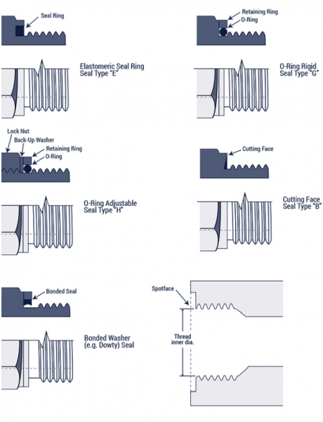
| Metric Thread Size | Metric Thread Size | Metric Thread Size |
| M8 x 1.0 | 8 | 7 |
| M10 x 1.0 | 10 | 9 |
| M12 x 1.5 | 12 | 10.5 |
| M14 x 1.5 | 14 | 12.5 |
| M16 x 1.5 | 16 | 14.5 |
| M18 x 1.5 | 18 | 16.5 |
| M20 x 1.5 | 20 | 18.5 |
| M22 x 1.5 | 22 | 20.5 |
| M24 x 1.5 | 24 | 22.5 |
| M26 x 1.5 | 26 | 24.5 |
| M27 x 1.5 | 27 | 25 |
| M33 x 1.5 | 33 | 31 |
| M36 x 1.5 | 36 | 34 |
| M42 x 1.5 | 42 | 40 |
| M45 x 1.5 | 45 | 43 |
| M48 x 1.5 | 48 | 46 |
Metric 60° Cone
DIN7631
| Pipe/Tube O.D. (mm) | Metric Thread Size | Male Thread O.D. (mm) | Female Thread I.D. (mm) |
| 6 | M12 x 1.5 | 12 | 10.5 |
| 8 | M14 x 1.5 | 14 | 12.5 |
| 10 | M16 x 1.5 | 16 | 14.5 |
| 12 | M18 x 1.5 | 18 | 16.5 |
| 15 | M22 x 1.5 | 22 | 20.5 |
| 18 | M26 x 1.5 | 26 | 24.5 |
| 22 | M30 x 1.5 | 30 | 28.5 |
| 28 | M38 x 1.5 | 38 | 36.5 |
| 35 | M45 x 1.5 | 45 | 43.5 |
| 52 | M52 x 1.5 | 52 | 50.5 |
Metric Tube Compression (DIN 2353 24° Cone)
| DIN 2353 L Tube O.D. (mm) | DIN 2353 S Tube O.D. (mm) | Metric Thread Size | Male Thread O.D. (mm) | Female Thread I.D. (mm) |
| 6 | M12 x 1.5 | 12 | 10.5 | |
| 8 | 6 | M14 x 1.5 | 14 | 12.5 |
| 10 | 8 | M16 x 1.5 | 16 | 14.5 |
| 12 | 10 | M18 x 1.5 | 18 | 16.5 |
| 12 | M20 x 1.5 | 20 | 18.5 | |
| 15 | 14 | M22 x 1.5 | 22 | 20.5 |
| 16 | M24 x 1.5 | 24 | 22.5 | |
| 18 | M26 x 1.5 | 26 | 24.5 | |
| 22 | 20 | M30 x 2.0 | 30 | 28 |
| 28 | 25 | M36 x 2.0 | 36 | 34 |
| 30 | M42 x 2.0 | 42 | 40 | |
| 35 | M45 x 2.0 | 45 | 43 | |
| 42 | 38 | M52 x 2.0 | 52 | 50 |
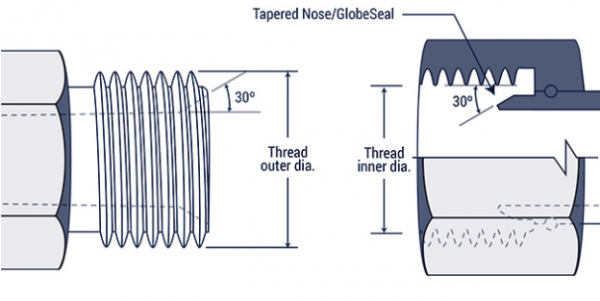
Japanese Industrial Standard JIS 300 Flare
| Inch Size | Dash Size | Thread Size | Male Thread | O.D. (in) | Female Thread | O.D. (in) |
| 1⁄8 | -2 | 1⁄8 - 28 | 3⁄8 | 0.38 | 11⁄32 | 0.35 |
| 1⁄4 | -4 | 1⁄4 - 19 | 33⁄64 | 0.52 | 15⁄32 | 0.47 |
| 3⁄8 | -6 | 3⁄8 - 19 | 21⁄32 | 0.65 | 19⁄32 | 0.60 |
| 1⁄2 | -8 | 1⁄2 - 14 | 13⁄16 | 0.82 | 3⁄4 | 0.75 |
| 5⁄8 | -10 | 5⁄8 - 14 | 7⁄8 | 0.88 | 13⁄16 | 0.80 |
| 3⁄4 | -12 | 3⁄4 - 14 | 1 1⁄32 | 1.04 | 31⁄32 | 0.97 |
| 1 | -16 | 1-11 | 1 5⁄16 | 1.30 | 1 7⁄32 | 1.22 |
| 1 1⁄4 | -20 | 1 1⁄4 - 11 | 1 21⁄32 | 1.65 | 1 9⁄16 | 1.56 |
| 1 1⁄2 | -24 | 1 1⁄2 - 11 | 1 7⁄8 | 1.88 | 1 25⁄32 | 1.79 |
| 2 | -32 | 2-11 | 2 11⁄32 | 2.35 | 2 1⁄4 | 2.26 |
Komatsu 30° Flare (JIS Metric)
| Dash Size | Metric Thread Size | Male Thread O.D. (mm) | Female Thread I.D. (mm) |
| -6 | M18 x 1.5 | 18 | 16.5 |
| -8 | M22 x 1.5 | 22 | 20.5 |
| -10 | M24 x 1.5 | 24 | 22.5 |
| -12 | M30 x 1.5 | 30 | 28.5 |
| -16 | M33 x 1.5 | 33 | 31.5 |
| -20 | M36 x 1.5 | 36 | 34.5 |
| -24 | M42 x 1.5 | 42 | 40.5 |